Convert Sheet Metal Sketches & Samples to Production-Ready CAD
Convert Sheet Metal Sketches & Samples to Production-Ready CAD
Why Legacy Parts or Napkin Sketches Delay Manufacturing Schedules
Buyers often see production stop when they hold only physical samples or napkin sketches and lack formal 3D models. Handling fabrication de tôles without drawings means sorting out missing engineering details before any cutting, bending, welding, or assembly starts. In these cases, sheet metal reverse engineering and hand sketch-to-CAD steps turn partial information into parts ready for production.
The Engineering Bottleneck in Product Development
Procurement managers and buyers without internal engineering teams often run into real hurdles when they launch new products or replace old hardware.
Lack of Dedicated CAD Resources: Small and mid-sized firms rarely keep full-time mechanical engineers on staff. They cannot build the detailed sheet metal fabrication drawings, flat patterns, or STEP files that shops expect.
Lost or Obsolete Technical Drawings: Legacy equipment projects usually call for reverse engineering sheet metal parts. Original files often sit lost, damaged, or exist only as old paper records from years ago.
Quoting Delays and Vendor Friction: Many contract manufacturers hold back quotes until they receive production-ready CAD drawings. This stretches out development timelines and adds friction between teams.
Costly Downtime and Sourcing Delays
Working from rough sketches without proper checks creates real risks once fabrication begins.
Tolerance Stack-Up Errors: Hand sketches rarely include allowances for metal thickness, bend relief, or internal clearances. These gaps lead to parts that do not fit as planned.
Misfit During Assembly: Sample part reverse engineering done without accurate bend data often produces seams that bind or mounting holes that sit out of place.
Unplanned Redesign Expenses: Trial-and-error runs without validated sheet metal CAD design raise costs and push back launch dates.
To close this gap, Quincaillerie SanJun works as an extension of the customer’s team. The company supports sheet metal fabrication without drawings by turning sample parts, reference dimensions, or sketches into files shops can use right away.
Reverse Engineering Techniques for Sheet Metal Enclosures
Transforming physical parts or hand sketches into detailed digital models requires accurate measurement and practical fabrication knowledge. Modern sheet metal reverse engineering connects existing physical geometry with repeatable digital manufacturing data.
Physical Sample Scanning and Measurement
Replicating existing enclosures requires a structured sample part reverse engineering process covering dimensions, material thickness, bends, holes, hardware, and assembly relationships.
3D Laser Scanning: 3D scanning can capture complex geometry, cutouts, hole positions, and enclosure contours during CAD from physical sample development.
K-Factor and Bend Allowance Calibration: Engineers review material thickness, bend radius, and forming behavior to recreate accurate flat patterns for reverse engineering sheet metal parts.
Hardware and Fastener Mapping: PEM studs, standoffs, nuts, hinges, and other hardware locations are mapped into the sheet metal CAD design to maintain alignment with mating assemblies.
A complete CAD-from-physical-sample workflow should reproduce not only visible dimensions but also the manufacturing logic required to fabricate the part consistently.
Translating Hand Sketches into Precision Enclosures
A structured sketch-to-CAD drawing process converts basic dimensional notes into usable engineering models and sheet metal fabrication drawings.
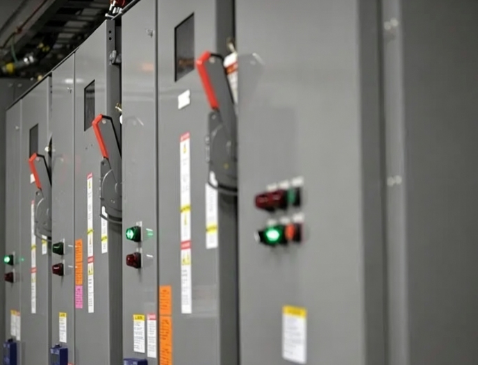
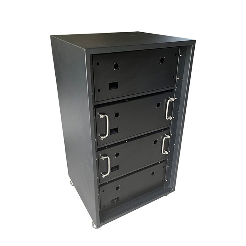
Structural Framework Modeling: A hand sketch to CAD workflow can convert dimensional concepts into rigid 3D models for products such as High/Low Voltage Distribution Cabinets.
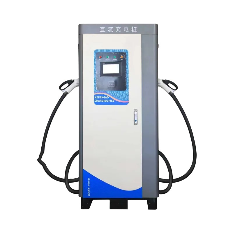
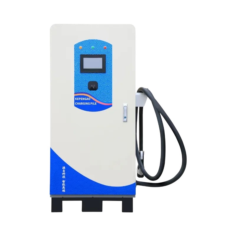
Application-Specific Feature Integration: Engineers can incorporate ventilation louvers, rain gutters, cable entries, and mounting interfaces into the sheet metal CAD design for products such as DC Charging Pile Enclosures.
Interference and Clearance Verification: Digital models help confirm internal spacing for wiring harnesses, breakers, cooling components, and other assemblies before physical fabrication.
This approach makes sheet metal fabrication without drawings possible while reducing the risk of interpreting a rough sketch differently during production.
Creating Production-Ready CAD Drawings and BOMs for Free
Moving from an initial concept to production requires more than a 3D model. Complete production-ready CAD drawings, BOMs, flat patterns, tolerances, and fabrication notes help translate the design into repeatable factory operations.
Design for Manufacturability (DFM) Integration
Integrating sheet metal DFM during early modeling prevents avoidable production problems. Strong design for manufacturability connects design intent with actual cutting, bending, welding, fastening, and finishing capabilities.
Standard Tooling Alignment: Sheet metal DFM adjusts bend radii and relief geometry to match available press brake tooling and reduce unnecessary special tooling.
Weld Seam and Joint Optimization: Design for manufacturability can introduce tab-and-slot joints or simplified seam locations to improve welding consistency and assembly efficiency.
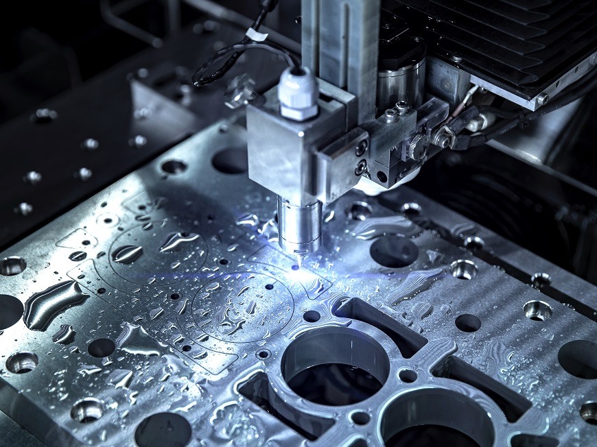
Material Utilization Efficiency: Flat patterns are optimized for nesting efficiency during fiber laser cutting, improving material utilization across sheet metal design and fabrication projects.
Complete BOM and Manufacturing Documentation
A complete engineering package provides the information needed for accurate production and inspection.
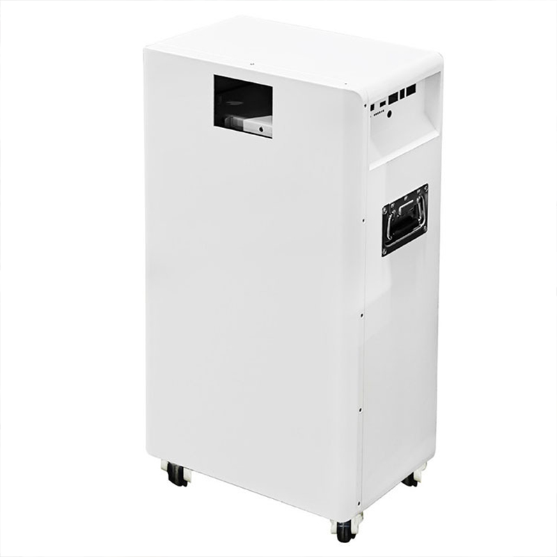
Detailed Bill of Materials (BOM): BOMs identify metal gauges, fasteners, hinges, sealing components, and related hardware for structures such as Energy Storage Cabinets.
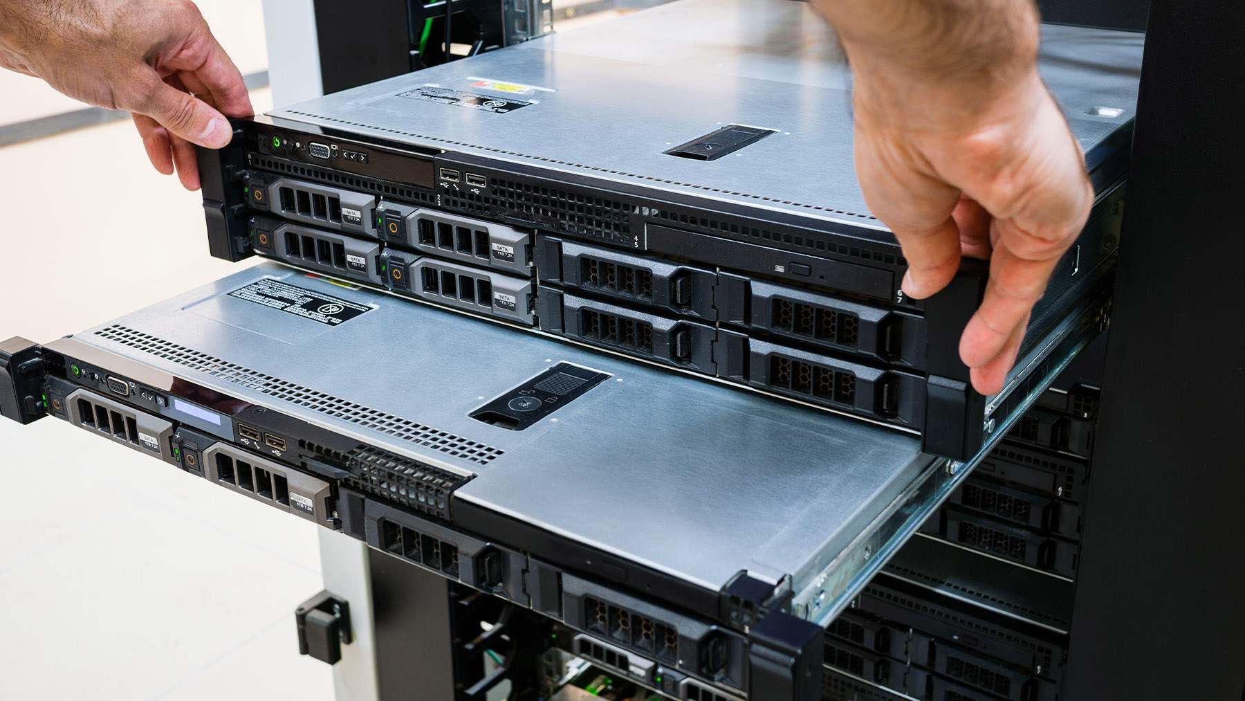
Exploded-View Assembly Drawings: Detailed sheet metal fabrication drawings can show assembly relationships for multi-part products such as Network Device Chassis.
2D Dimensioned Inspection Prints: Production-ready CAD drawings include key dimensions, tolerances, and inspection requirements for quality-control verification.
How SanJun Hardware Translates Concept Ideas into Physical Prototypes
Once the digital package is approved, sheet metal prototype manufacturing converts the validated design into a physical part for functional and assembly testing. SanJun Hardware supports the transition from early engineering validation through prototype to mass production.
Rapid Prototyping with Low MOQ
Flexible sheet metal prototype manufacturing allows buyers to validate fit, appearance, and function before committing to larger production volumes.
Flexible 1-Piece MOQ: Customers can evaluate a physical prototype before approving full-scale fabrication.
Rapid Turnaround Sampling: Fiber laser cutting and CNC press brake bending support efficient sheet metal prototype manufacturing for custom enclosures and structural parts.
Custom Surface Finishing: Powder coating, painting, anodizing, and other finishes can be incorporated during prototype development to evaluate final appearance.
Seamless Transition from Prototype to Mass Production
A controlled prototype-to-mass-production process ensures that approved design and manufacturing parameters remain consistent as order volume increases.
Process Standardization: Verified cutting paths, bend sequences, welding fixtures, and inspection criteria are documented after prototype approval.
Scalable Enclosure Fabrication: Approved sheet metal design and fabrication workflows can be scaled for products such as Self-Service Kiosk Enclosures and industrial control boxes.
Strict Quality Assurance: Dimensional inspection, coating checks, and application-specific testing help preserve consistency during prototype to mass production.
Ready to Turn Your Sketch or Sample Part into Production-Ready Sheet Metal?
Don’t let missing files delay your project. Whether you need sheet metal reverse engineering, CAD from a physical sample, sketch to CAD drawing, or complete sheet metal fabrication drawings, SanJun Hardware can help convert your concept into a manufacturable design.
Upload your hand sketch or send a sample part to SanJun Hardware for sheet metal CAD design, sheet metal DFM, prototype development, and production planning.
Q: How is sheet metal fabrication without drawings done?
A: Sheet metal fabrication without drawings is typically done by sample part reverse engineering, precision measuring, 3D scanning, or sketch-to-CAD drawing. Then engineers will make flat patterns, 3D models, tolerances, and ready-to-fabricate drawings in CAD.
Q: What is required when reverse engineering sheet metal parts?
A: The geometry, material thickness, bend radii, holes, fasteners, and assembly relationship of sheet metal parts need to be measured; then the information is transferred into CAD by using physical samples, which is then verified by sheet metal DFM.
Q: What information is needed to make a sketch to CAD drawing?
A: Sketch to CAD drawing needs overall dimensions, material, approximate thickness, hole positions, mounting requirements, working environment, and clearance information.
Q: Why is design for manufacturability important before sheet metal prototype manufacturing?
A: Design for manufacturability identifies difficult bend radii, clearance issues, inefficient joints, and material waste before sheet metal prototype manufacturing.
Oui. Nous acceptons une commande minimum de 1 pièce, sans besoin d'outillage. Tous les boîtiers en tôle personnalisés peuvent être produits directement selon votre conception.
Oui, nous acceptons la fabrication de pièces métalliques sur mesure strictement basée sur vos dessins 2D/3D. Nous offrons une vérification DFM gratuite, suivons vos exigences exactes en matière de matériaux, de tolérances et de finitions. La production de prototypes et la production de masse sont disponibles avec un contrôle qualité complet et un emballage conforme aux normes d'exportation.
Absolument. Indiquez-nous les dimensions de votre produit, sa fonction d'assemblage, son scénario d'utilisation et vos exigences de performance. Notre équipe de tôlerie vous propose gratuitement la conception structurelle, l'optimisation de la solution et l'analyse de fabricabilité (DFM).
Vous n'avez pas besoin de réaliser les plans ; nous prenons en charge l'intégralité du travail de conception, de l'esquisse au plan de production, afin de réduire vos coûts et risques de R&D. Nous procédons à des révisions des plans à plusieurs reprises pour garantir une intégration parfaite à vos besoins.
Nous fournissons une révision de dessin DFM sous 24 heures et un devis formel après réception de vos exigences techniques.
Oui. Nous proposons un échantillonnage rapide de prototypes selon vos dessins, vous aidant à vérifier la structure et la taille avant la commande en gros.
Tous nos produits ont obtenu les certifications ISO9001, EMC, LVD et RoHS.
Nous respectons pleinement les normes mondiales de sécurité et de qualité, en fournissant des solutions stables et fiables pour toutes les applications de projet.
Nous gérons notre propre usine et proposons une production intégrale en interne, de A à Z.
Un contrôle de processus rigoureux et une gestion de la qualité standardisée garantissent une qualité de produit stable et des livraisons ponctuelles, construisant ainsi des partenariats mondiaux fiables et durables.
Nous traitons toute une gamme de matériaux de tôlerie standard et haute performance, y compris l'acier inoxydable (304/316), l'aluminium (5052/6061), l'acier laminé à froid/chaud, l'acier galvanisé, le laiton et le cuivre. Nous pouvons également nous procurer des matériaux spéciaux selon les exigences de votre projet.
Notre tolérance d'usinage standard est de ±0,1 mm pour la découpe laser et le pliage. Pour les pièces de haute précision, nous pouvons atteindre une tolérance de ±0,05 mm en fonction de l'épaisseur du matériau et de la structure de la pièce. Toutes les dimensions sont contrôlées selon la norme 100% avant la livraison afin de répondre à vos exigences.
Oui, nous fournissons des services complets de traitement de surface tout-en-un, incluant le revêtement en poudre, la peinture, l'anodisation, le sablage, le brossage, la galvanoplastie, la passivation, le polissage et le traitement thermique. Nous pouvons personnaliser les couleurs et les effets selon votre conception.
Oui, nous signons toujours un accord de non-divulgation (NDA) avant de recevoir des dessins ou des détails de conception de nos clients. Nous protégeons strictement votre propriété intellectuelle et gardons tous vos projets confidentiels.




























Laisser un commentaire