Convert Sheet Metal Sketches & Samples to Production-Ready CAD
Convert Sheet Metal Sketches & Samples to Production-Ready CAD
Why Legacy Parts or Napkin Sketches Delay Manufacturing Schedules
Buyers often see production stop when they hold only physical samples or napkin sketches and lack formal 3D models. Handling fabricação de metal de folhas without drawings means sorting out missing engineering details before any cutting, bending, welding, or assembly starts. In these cases, sheet metal reverse engineering and hand sketch-to-CAD steps turn partial information into parts ready for production.
The Engineering Bottleneck in Product Development
Procurement managers and buyers without internal engineering teams often run into real hurdles when they launch new products or replace old hardware.
Lack of Dedicated CAD Resources: Small and mid-sized firms rarely keep full-time mechanical engineers on staff. They cannot build the detailed sheet metal fabrication drawings, flat patterns, or STEP files that shops expect.
Lost or Obsolete Technical Drawings: Legacy equipment projects usually call for reverse engineering sheet metal parts. Original files often sit lost, damaged, or exist only as old paper records from years ago.
Quoting Delays and Vendor Friction: Many contract manufacturers hold back quotes until they receive production-ready CAD drawings. This stretches out development timelines and adds friction between teams.
Costly Downtime and Sourcing Delays
Working from rough sketches without proper checks creates real risks once fabrication begins.
Tolerance Stack-Up Errors: Hand sketches rarely include allowances for metal thickness, bend relief, or internal clearances. These gaps lead to parts that do not fit as planned.
Misfit During Assembly: Sample part reverse engineering done without accurate bend data often produces seams that bind or mounting holes that sit out of place.
Unplanned Redesign Expenses: Trial-and-error runs without validated sheet metal CAD design raise costs and push back launch dates.
To close this gap, SanJun Hardware works as an extension of the customer’s team. The company supports sheet metal fabrication without drawings by turning sample parts, reference dimensions, or sketches into files shops can use right away.
Reverse Engineering Techniques for Sheet Metal Enclosures
Transforming physical parts or hand sketches into detailed digital models requires accurate measurement and practical fabrication knowledge. Modern sheet metal reverse engineering connects existing physical geometry with repeatable digital manufacturing data.
Physical Sample Scanning and Measurement
Replicating existing enclosures requires a structured sample part reverse engineering process covering dimensions, material thickness, bends, holes, hardware, and assembly relationships.
3D Laser Scanning: 3D scanning can capture complex geometry, cutouts, hole positions, and enclosure contours during CAD from physical sample development.
K-Factor and Bend Allowance Calibration: Engineers review material thickness, bend radius, and forming behavior to recreate accurate flat patterns for reverse engineering sheet metal parts.
Hardware and Fastener Mapping: PEM studs, standoffs, nuts, hinges, and other hardware locations are mapped into the sheet metal CAD design to maintain alignment with mating assemblies.
A complete CAD-from-physical-sample workflow should reproduce not only visible dimensions but also the manufacturing logic required to fabricate the part consistently.
Translating Hand Sketches into Precision Enclosures
A structured sketch-to-CAD drawing process converts basic dimensional notes into usable engineering models and sheet metal fabrication drawings.
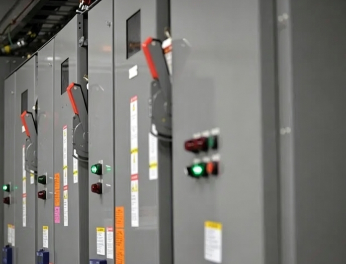
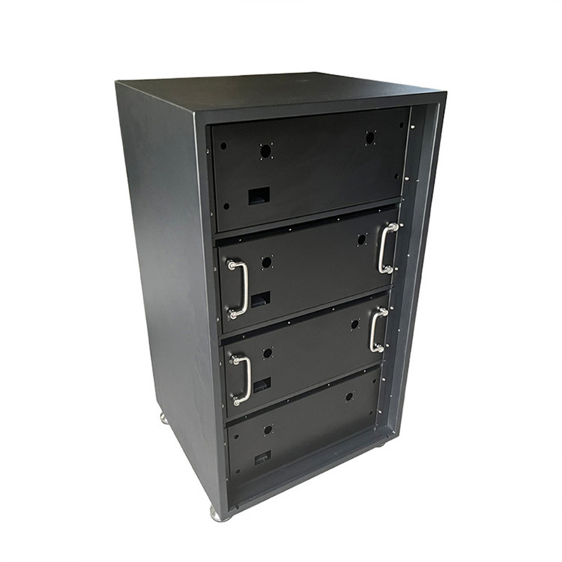
Structural Framework Modeling: A hand sketch to CAD workflow can convert dimensional concepts into rigid 3D models for products such as High/Low Voltage Distribution Cabinets.
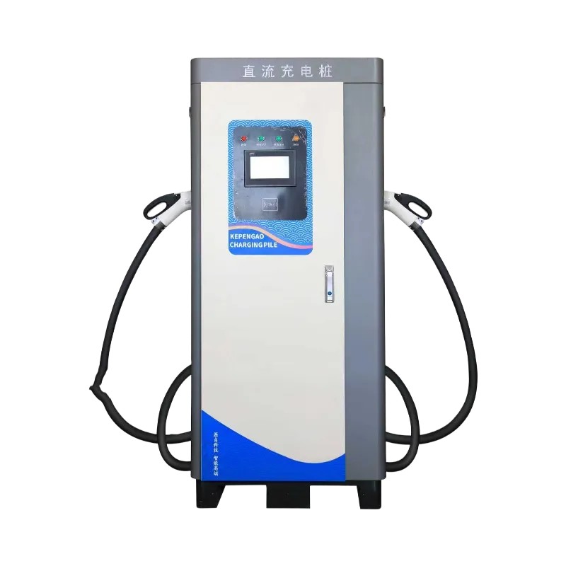
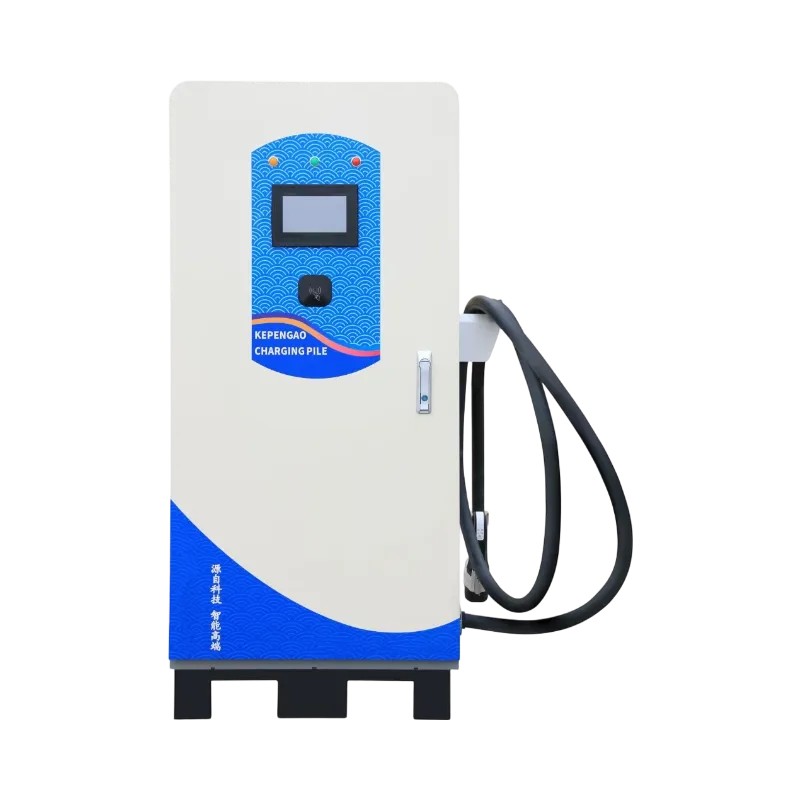
Application-Specific Feature Integration: Engineers can incorporate ventilation louvers, rain gutters, cable entries, and mounting interfaces into the sheet metal CAD design for products such as DC Charging Pile Enclosures.
Interference and Clearance Verification: Digital models help confirm internal spacing for wiring harnesses, breakers, cooling components, and other assemblies before physical fabrication.
This approach makes sheet metal fabrication without drawings possible while reducing the risk of interpreting a rough sketch differently during production.
Creating Production-Ready CAD Drawings and BOMs for Free
Moving from an initial concept to production requires more than a 3D model. Complete production-ready CAD drawings, BOMs, flat patterns, tolerances, and fabrication notes help translate the design into repeatable factory operations.
Design for Manufacturability (DFM) Integration
Integrating sheet metal DFM during early modeling prevents avoidable production problems. Strong design for manufacturability connects design intent with actual cutting, bending, welding, fastening, and finishing capabilities.
Standard Tooling Alignment: Sheet metal DFM adjusts bend radii and relief geometry to match available press brake tooling and reduce unnecessary special tooling.
Weld Seam and Joint Optimization: Design for manufacturability can introduce tab-and-slot joints or simplified seam locations to improve welding consistency and assembly efficiency.
Material Utilization Efficiency: Flat patterns are optimized for nesting efficiency during fiber laser cutting, improving material utilization across sheet metal design and fabrication projects.
Complete BOM and Manufacturing Documentation
A complete engineering package provides the information needed for accurate production and inspection.
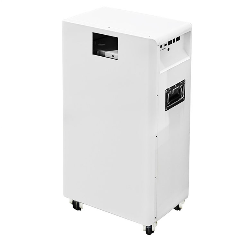
Detailed Bill of Materials (BOM): BOMs identify metal gauges, fasteners, hinges, sealing components, and related hardware for structures such as Energy Storage Cabinets.
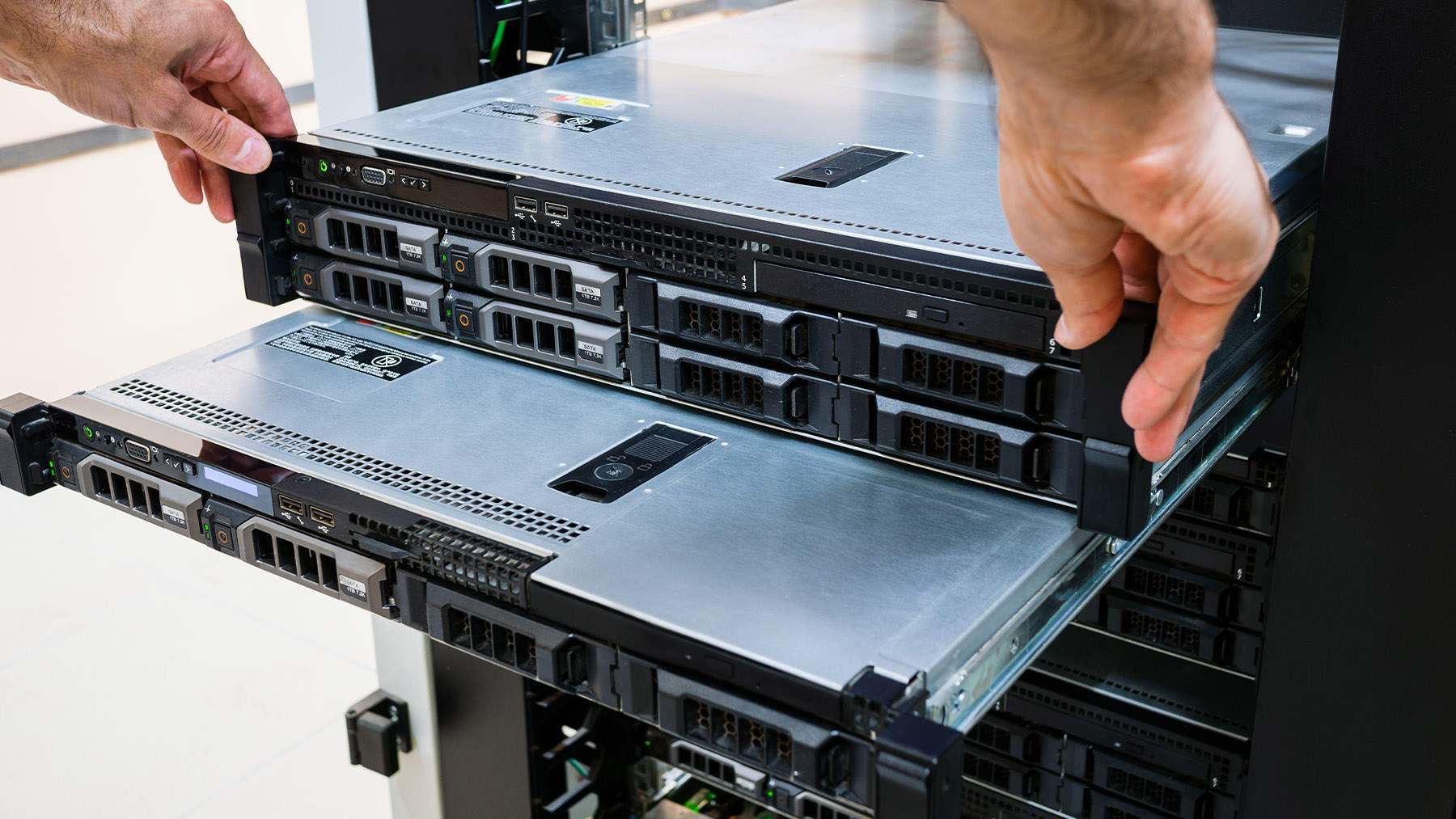
Exploded-View Assembly Drawings: Detailed sheet metal fabrication drawings can show assembly relationships for multi-part products such as Network Device Chassis.
2D Dimensioned Inspection Prints: Production-ready CAD drawings include key dimensions, tolerances, and inspection requirements for quality-control verification.
How SanJun Hardware Translates Concept Ideas into Physical Prototypes
Once the digital package is approved, sheet metal prototype manufacturing converts the validated design into a physical part for functional and assembly testing. SanJun Hardware supports the transition from early engineering validation through prototype to mass production.
Rapid Prototyping with Low MOQ
Flexible sheet metal prototype manufacturing allows buyers to validate fit, appearance, and function before committing to larger production volumes.
Flexible 1-Piece MOQ: Customers can evaluate a physical prototype before approving full-scale fabrication.
Rapid Turnaround Sampling: Fiber laser cutting and CNC press brake bending support efficient sheet metal prototype manufacturing for custom enclosures and structural parts.
Custom Surface Finishing: Powder coating, painting, anodizing, and other finishes can be incorporated during prototype development to evaluate final appearance.
Seamless Transition from Prototype to Mass Production
A controlled prototype-to-mass-production process ensures that approved design and manufacturing parameters remain consistent as order volume increases.
Process Standardization: Verified cutting paths, bend sequences, welding fixtures, and inspection criteria are documented after prototype approval.
Scalable Enclosure Fabrication: Approved sheet metal design and fabrication workflows can be scaled for products such as Self-Service Kiosk Enclosures and industrial control boxes.
Strict Quality Assurance: Dimensional inspection, coating checks, and application-specific testing help preserve consistency during prototype to mass production.
Ready to Turn Your Sketch or Sample Part into Production-Ready Sheet Metal?
Don’t let missing files delay your project. Whether you need sheet metal reverse engineering, CAD from a physical sample, sketch to CAD drawing, or complete sheet metal fabrication drawings, SanJun Hardware can help convert your concept into a manufacturable design.
Upload your hand sketch or send a sample part to SanJun Hardware for sheet metal CAD design, sheet metal DFM, prototype development, and production planning.
Q: How is sheet metal fabrication without drawings done?
A: Sheet metal fabrication without drawings is typically done by sample part reverse engineering, precision measuring, 3D scanning, or sketch-to-CAD drawing. Then engineers will make flat patterns, 3D models, tolerances, and ready-to-fabricate drawings in CAD.
Q: What is required when reverse engineering sheet metal parts?
A: The geometry, material thickness, bend radii, holes, fasteners, and assembly relationship of sheet metal parts need to be measured; then the information is transferred into CAD by using physical samples, which is then verified by sheet metal DFM.
Q: What information is needed to make a sketch to CAD drawing?
A: Sketch to CAD drawing needs overall dimensions, material, approximate thickness, hole positions, mounting requirements, working environment, and clearance information.
Q: Why is design for manufacturability important before sheet metal prototype manufacturing?
A: Design for manufacturability identifies difficult bend radii, clearance issues, inefficient joints, and material waste before sheet metal prototype manufacturing.
Sim. Apoiamos uma MOQ de 1PC, não é necessária a criação de moldes. Todas as caixas personalizadas de chapa metálica podem ser produzidas diretamente de acordo com o seu design.
Sim, aceitamos fabrico de chapa metálica personalizado estritamente com base nos seus desenhos 2D/3D. Fornecemos verificação DFM gratuita, seguimos os seus requisitos exatos de material, tolerância e acabamento. Estão disponíveis tanto protótipos como produção em massa, com controlo de qualidade total e embalagens de exportação standard.
Com certeza. Envie-nos as dimensões do seu produto, a função de montagem, o cenário de uso e as exigências de desempenho. Nossa equipe de chapas metálicas oferece projeto estrutural gratuito, ajuste de soluções e análise DFM.
Você não precisa preparar desenhos; nós cuidamos de todo o trabalho de projeto, do esboço ao desenho de produção, para que você economize custos e riscos de P&D. Revisamos os desenhos repetidamente para atender perfeitamente às suas necessidades de montagem.
Fornecemos revisão de desenhos DFM 24H e cotação formal após a receção dos seus requisitos técnicos.
Sim. Oferecemos prototipagem rápida de amostras de acordo com os seus desenhos, ajudando-o a verificar a estrutura e o tamanho antes de uma encomenda em massa.
Todos os nossos produtos obtiveram as certificações ISO9001, EMC, LVD e RoHS.
Cumprimos integralmente as normas globais de segurança e qualidade, fornecendo soluções estáveis e confiáveis para todas as aplicações de projetos.
Operamos a nossa própria fábrica e fornecemos produção completa interna "one-stop".
Um controlo de processo rigoroso e uma gestão de qualidade padronizada garantem uma qualidade de produto estável e entregas pontuais, construindo parcerias globais fiáveis a longo prazo.
Processamos uma gama completa de materiais de chapa metálica padrão e de alto desempenho, incluindo aço inoxidável (304/316), alumínio (5052/6061), aço laminado a frio/quente, aço galvanizado, latão e cobre. Podemos também adquirir materiais especiais de acordo com os requisitos do seu projeto.
A nossa tolerância padrão de maquinagem é de ±0,1 mm para corte a laser e dobragem. No caso de peças de alta precisão, podemos atingir ±0,05 mm, dependendo da espessura do material e da estrutura da peça. Todas as dimensões são inspecionadas de acordo com a norma 100% antes da entrega, para cumprir os seus requisitos.
Sim, prestamos serviços completos de tratamento de superfícies, incluindo pintura a pó, pintura, anodização, jateamento de areia, escovagem, galvanoplastia, passivação, polimento e tratamento térmico. Podemos personalizar cores e efeitos de acordo com o seu design.
Sim, assinamos sempre um NDA (Acordo de Não Divulgação) antes de receber quaisquer desenhos ou detalhes de design dos clientes. Protegemos rigorosamente a sua propriedade intelectual e mantemos todos os seus projetos confidenciais.




























Deixe um comentário